
Project and Turnaround Support
-
Close critical gaps with seasoned engineers who slot into your processes on day one. Refined Engineering provides on-site (or hybrid) support to surge for turnarounds, projects, and reliability—while maintaining code alignment and documentation discipline.
What we provide
Mechanical/static, project, and reliability engineers embedded with your team
Turnaround/outage coverage (days/nights), shift flexibility, and rapid mobilization
Safety-ready personnel (site orientation, TWIC/backgrounds as required); PPE and tooling standards
Optional PE oversight/responsible charge available where scope requires
Typical roles we fill
Mechanical/Static: pressure equipment, piping, and tank engineering (ASME VIII/B31.3, API 650/620)
Owner’s Engineer: vendor coordination, submittal/TQ management, bid tabs, and shop/factory visits
Project/TA Engineering: scope development, estimates, planning, ITPs, field engineering and walkdowns
Reliability/MI: API 510/570/653 interfaces, bad actor elimination, corrosion circuit coordination
How we integrate
Kickoff alignment on scope, procedures, and KPIs; clear RASCI with your stakeholders
Plug-in to your tools (SAP/Maximo, document control, CMMS, MOC, DMS/CAD)
Weekly cadence: risk/issue log, look-ahead, and decision register; transparent change control
Typical tasks
Field engineering, redlines, and RFI resolution; vendor drawing/calculation reviews
Turnaround workpacks, lift/rigging checks, tie-in planning, punchlists, and test packages
Budget/schedule realism checks, progress reporting, and closeout documentation
Light calculations and screening checks on site; deeper analyses routed through our office as needed
Deliverables
Weekly status reports and KPI dashboard; risk/decision logs and action trackers
Approved workpacks, marked drawings, and turnover dossiers (MDR-ready)
Closeout summary with lessons learned and backlog/deferral recommendations
Owner-ready outcomes
Immediate capacity to hit milestones and de-risk outages
Fewer RFIs and smoother handoffs between field, vendors, and design teams
Consistent, auditable documentation that stands up to client and regulatory review
-
Hit scope, hit schedule, and start up clean. Refined Engineering embeds with your team to plan, execute, and close out outages—keeping safety, code compliance, and documentation front and center.
Before the outage (plan & prepare)
Scope definition and freeze; risk register and critical path review
Workpacks: isolation plans/blind lists, tie-in details, lift/rigging checks, hydro/leak test boundaries, ITPs, and QA hold points
Vendor readiness: bid tabs, submittal reviews, spare/kit verification, shop visits/FAT alignment
Materials & calcs: t_min checks, rerate screens, flange torque/tension tables (PCC-1), temporary support/stability notes
Procedures: demob/removal/installation sequences, PWHT plans (WRC 452), PSV handling/testing coordination
During the outage (field execution)
On-site field engineering and redlines; RFI triage and rapid calc checks
Daily walkdowns, punchlist management, NCR/CAPA closure, and weld/NDE oversight
Exchanger/column internal fit checks, nozzle load/alignments, piping support adjustments
Turnaround control room support: progress KPIs, decision log, emergent-work scoping with schedule/cost impacts
Startup & turnover (finish strong)
Pressure/leak tests, reinstatement, and flange management verification
PSV reinstatement, setpoint confirmations, and relief documentation updates
PSSR/commissioning support, operating envelope confirmation (pressure/temp/ramp)
Turnover dossiers: MDR, updated P&IDs/isos, datasheets, and as-built sketches
Deliverables
Approved workpacks and field checklists; torque/tension tables and test procedures
Daily status reports with risks, constraints, and mitigation actions
PE-reviewed notes/calcs where required; organized turnover package ready for audit
Owner-ready outcomes
Safer execution with fewer RFIs and rework
Schedule discipline through clear engineering decisions on the critical path
Clean startup and traceable documentation that satisfies clients, insurers, and regulators
-
When the unexpected happens, you need fast, defensible engineering. Refined Engineering mobilizes quickly—remotely or on-site—to stabilize conditions, protect people and assets, and chart the shortest safe route to recovery.
When to call us
Leaks/ruptures, overpressure/vacuum events, exchanger or column upsets
Fire/heat exposure, impacts/dropped objects, storm or freeze damage, power trips
Startup/shutdown excursions, relief device anomalies, flange/joint failures
What we do (immediately)
Incident triage with ops/ICS: isolate, depressure/vent, establish safe envelopes
Make-safe checks: temporary supports/shoring, hot/cold work limits, leak-mitigation options
Rapid engineering screens: MAWP/MDMT sanity, external pressure/vacuum risk, flange torque/tension (PCC-1), nozzle/load checks
Relief/device review: setpoints, blocked-in/thermal cases, temporary protection strategies
Evidence plan for later RCA (without slowing recovery)
Stabilize & recover (next 24–72 hours)
Focused FFS screening (API 579 Level-1/targeted Level-2) for metal loss, distortion, dents/gouges, brittle fracture, hydrogen or fire damage
Hot-spot/temporary derate envelopes (pressure/temperature/ramp) and monitored operations plans
Vendor & contractor coordination: temporary repair concepts, test boundaries, ITP/hold points
Regulator/insurer support and clear communications for leadership and the field
How we work
Integrate with your Incident Command/System of record; maintain a decision log and RFI tracker
PE oversight available; stamped emergency engineering notes where jurisdictionally required
Escalate to advanced analysis (VIII-2 Part 5/FEA) only when it changes a critical decision
Deliverables
Emergency Engineering Memo: hazards, limits, and required controls (owner-approved)
Temporary operating envelope (pressure/temp/vacuum), flange/joint settings, and test procedures
Field sketches/redlines, checklists, and turnback criteria for restart
Daily status summaries; close-out package with actions, assumptions, and MDR updates
Owner-ready outcomes
Faster, safer stabilization with fewer secondary incidents
Clear, auditable basis for decisions under ASME/API and site procedures
Shorter time to a clean restart—and better inputs for subsequent root-cause analysis
-
Your independent technical advocate—from concept to startup. Refined Engineering safeguards scope, cost, and safety, keeping EPCs and vendors aligned while assuring code-compliant, operable, and maintainable outcomes.
What we do
Scope & requirements: Basis of Design stewardship, stage-gate readiness, value engineering, and decision logs.
Procurement support: mechanical specs, vendor lists, RFQs, bid tabs, TQs/deviation control, and negotiations.
Design assurance: PFD/P&ID and layout reviews, datasheet checks, spot-verification of calcs, materials/corrosion selection, ASME/API/OSHA compliance.
Fabrication quality: VDRL/VDSL management, ITPs and hold points, shop audits, FAT/SAT witnessing, NCR/CAPA closure.
Constructability & operations: tie-in planning, access/lifting, turnaround constraints, modularization, and maintainability checks.
Risk & governance: schedule/cost realism, change management, interface control, and weekly KPI reporting.
Field & commissioning: site engineering support, punchlists, test packages, PSSR, procedures, spares, and clean turnover dossiers (MDR).
How we work
Single-point technical leadership with PE oversight as required
Transparent RFI/TQ tracking, revision control, and audit-ready documentation
Alignment with your systems (CMMS/DMS/MOC) and safety processes
Deliverables
Comment/resolution logs and approval matrices
PE-reviewed design notes, calculation spot-checks, and compliance letters
Bid evaluations, shop/field visit reports, ITPs/FAT records, and turnover packages
Owner-ready outcomes
Fewer change orders and claims; stronger contractual leverage
Designs that start up clean—code-compliant and maintainable
Clear visibility to scope, risks, and progress from day one
Sample Projects
-

Turnaround Engineering Support
1. Main Problem Identified: A refinery unit faced a compressed 28-day outage with an overloaded worklist—column tray repairs, heater convection coil replacement, two new tie-ins, and more than 500 controlled flange breaks—creating high risk to the critical path and a leak-free startup. Historic delays were tied to late field RFIs, incomplete test packages, and inconsistent flange assembly practices that produced hot-start leaks.
2. Approach: A two-engineer on-site team provided 24/7 field engineering and QA/QC, owning RFI triage, weld mapping, and mechanical-integrity hold points while running daily SIMOPS and critical-path reviews with construction and operations. We built and issued pressure-test packages, executed controlled flange management per PCC-1 (torque/tension tables, gasket QA), coordinated NDE (MT/PT/UT/PAUT) and PWHT, and closed discovery work via rapid calcs and red-lined drawings for approval. Pre-startup, we led line walks and reinstatement (blind lists, LOTO clearance, torque verification, hydro/pneumatic tests) and delivered as-built P&IDs and turnover dossiers.
3. End Results: The unit achieved mechanical complete on day 26 and met the day-28 window, with zero recordable incidents and a leak-free startup across 100+ flange breaks. Critical-path tasks (heater coil swap and tower tray repairs) finished with at least 18 hours of float, and discovery work—19 additional welds and two nozzle repads—was absorbed without schedule slip or capital variance. The engagement delivered a reusable flange-management toolkit and updated test-package templates, reducing next-outage planning time and setting a standard for future turnarounds.
-

Emergency Repair Plan Development and Certification
1. Main Problem Identified: High-pressure low-temperature separator built to ASME Section VIII, Division 2 required a repair plan and certification by a licensed professional engineer to ensure compliance with NBIC and ASME Section VIII-2.
2. Approach: Reviewed User’s Design Specification (UDS), Manufacturer’s Data Report (MDR), PWHT procedures, weld overlays, and insulation installation methods in accordance with NBIC NB-23 Part 3 rules. Developed the details of the repair plan in conjunction with client specifications and requirements.
3. End Results: The PE certified repair plan was provided to the client as complete and code-compliant; approved for implementation under National Board Inspection Code guidelines. Repairs were completed and the vessel was put back into service successfully.
-
Purchasing Specification Creation
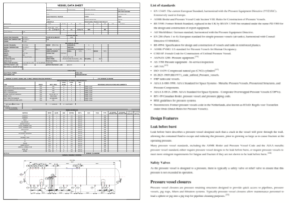
1. Main Problem Identified: An in-service reactor vessel had widespread internal erosion, driving remaining wall below site minimums and making repair uneconomical ahead of a planned turnaround. A replacement was required, but prior procurements suffered from inconsistent vendor assumptions that led to change orders, nozzle misalignment, and schedule risk.
2. Approach: A comprehensive Mechanical Purchasing Specification (M-Spec) was authored to define design and construction requirements per ASME Section VIII, Division 1 with supplementary analysis where nozzle external loads warranted, including MAWP/MDMT, corrosion allowance, materials, impact testing, NDE, PWHT, coatings, and nameplate/U-stamp requirements. The deliverables included purchasing and bid requirements (schedule, pricing breakdown, exceptions register), a process/mechanical datasheet, conceptual GA drawings with nozzle map and allowable external loads, and a vendor data/ITP matrix with hold points, MDR content, shipping/lifting instructions, and preservation criteria.
3. End Results: The standardized package yielded three fully compliant “apples-to-apples” bids with fewer than five minor exceptions, eliminating scope ambiguity across vendors. The selected fabricator committed to an acceptable turnaround cycle and a cost reduction versus the last comparable buy, and IFC vendor drawings matched existing foundations and centerlines with minimal RFIs during installation. The new vessel entered service with leak-free performance and documentation complete for turnover.
-
Emergency FFS to Restart Unit
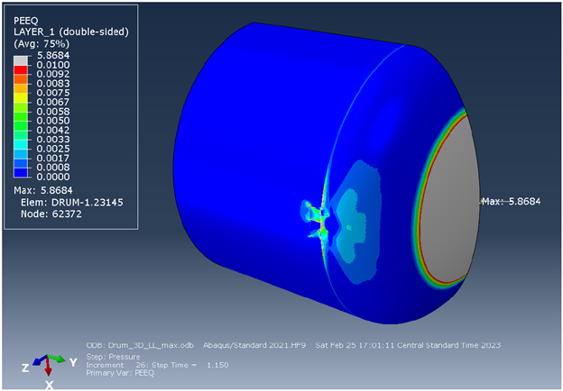
1. Main Problem Identified: Inspection found crack-like indications on the outer shell near the head-to-shell weld of a recycle-service vessel; attempts to grind out the defects were unsuccessful, leaving several small flaws within locally thinned cavities. The evidence pointed to stress corrosion cracking driven by chlorides in insulation or fluoride exposure, and the weld discontinuity at the head junction meant a higher-rigor assessment was warranted.
2. Approach: A Level 3 fitness-for-service evaluation per API 579/ASME FFS-1 was performed, modeling the local thinned areas with a nonlinear limit-load analysis and developing a through-wall stress profile for crack assessment. Crack stability was checked using Part 9 Failure Assessment Diagram methods with conservative assumptions (infinite-length surface crack at measured depth, residual weld stresses), while Part 5 addressed the LTAs under design pressure loading with appropriate symmetry constraints.
3. End Results: Both the LTA and crack assessments were acceptable for continued service: the limit-load model showed margin and the crack assessment points plotted below the FAD acceptance curve. To manage the SCC mechanism and risk, recommendations included applying a removable external barrier, initiating close post-startup monitoring (about monthly initially), and recognizing that with 316SS toughness any progression would likely present as leakage rather than catastrophic fracture; longer-term run/replace decisions were tied to risk tolerance.
-
Amine Stripper FFS during Turnaround
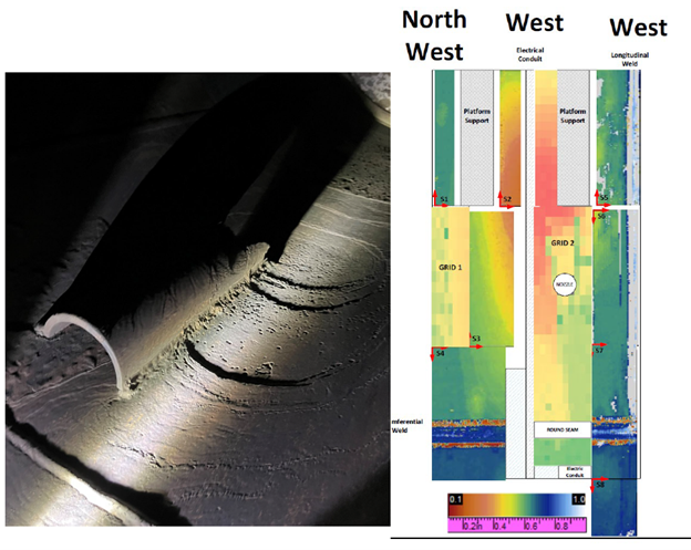
1. Main Problem Identified: Local thin areas were discovered on the second bottom shell course of an amine stripper vessel, prompting a fitness-for-service evaluation. The assessment considered the design condition and included site loads, while external pressure was excluded via administrative controls.
2. Approach: A Part 5 Level 3 assessment per API 579 used elastic-plastic analysis requiring convergence at an effective load factor of 3.6 for plastic-collapse acceptance; buckling was evaluated by ASME VIII-2 Method B using an eigenvalue-derived imperfection equal to 1% of vessel diameter with a stability target of ≥ 1.67. Global loads were calculated in COMPRESS and applied to a bottom-section FE model that incorporated measured thickness mapping and corrosion allowances. The load set included pressure thrust, deadweight, wind shear/bending, and platform clip loads.
3. End Results: The vessel satisfied the acceptance criteria—plastic-collapse cases and buckling analysis achieved acceptable load factors. The evaluation found the component acceptable with RSF = 0.9 and a 1/16-in future corrosion allowance at the LTA, recommended re-inspection in six months, and treated external pressure by administrative control rather than calculation.
Connect with an Engineer
Contact us today for support with your pressure equipment design and analysis needs.