
Suitability and Compliance Assessments
-
Turn unknowns into a defensible design basis. Refined Engineering reconstructs the technical record for legacy or poorly documented vessels, exchangers, piping, and tanks—so you can operate, modify, and inspect with confidence.
What we recover & verify
Asset identification: nameplates, National Board/jurisdictional records, service history
Materials & geometry: PMI, thickness/UT grids, weld/heat maps, dimensions/ovality, nozzle schedules
Operating basis: pressures/temperatures, corrosion circuits/rates, PSV/vent configurations, prior alterations
Engineering outputs
Reconstructed design basis with code/edition control (ASME VIII-1/2, B31.3, API 650/620)
MAWP/MDMT, external pressure, wind/seismic, nozzle reinforcement summaries
Relief revalidation and setpoints per API 520/521/2000; device datasheets and orifice checks
Owner/user rerate forms and supplemental nameplate wording (as applicable)
Program & compliance alignment
API 510/570/653, NBIC documentation expectations; MOC inputs and MI file structure
Variance/State Special support where required by jurisdiction
Field data & QA
Structured data sheets, photo logs, drawing redlines/sketches
Independent QA of third-party NDE, hardness checks for sour service, assumptions/gaps register
Deliverables
PE-sealed evaluation report and calculation package
Updated datasheets, GA/nozzle sketches, relief documentation, and transmittal index
TQ/deviation log, clear limitations/conditions of use, and organized digital MDR/asset file
Owner-ready outcomes
Audit-ready records for previously undocumented equipment
Clear operating limits and setpoints, fewer RFIs, faster approvals
A maintainable baseline for inspection, reliability, and future projects
-
Quick, code-aligned confirmation that equipment can safely perform in its intended service. Refined Engineering executes suitability assessments—modeled on API 579 Level-1 screening—to verify vessels, exchangers, piping, and tanks are appropriate for stated design and operating conditions.
What we check
Design basis & service: pressures/temperatures, fluids, corrosion circuits/rates, sour-service needs (e.g., NACE MR0175/ISO 15156)
Materials & thickness: nameplate/data review, joint efficiency, t_min vs. measured thickness, CA validation
MAWP/MDMT screening: basic checks for pressure, temperature, external pressure/vacuum, and brittle-fracture limits
Local features: simplified reviews of nozzles/branches, supports/lugs, and typical discontinuities
Relief alignment: sanity check of PSV/vent setpoints and scenarios (API 520/521/2000) with current MAWP/service
Piping sanity checks: B31.3 hoop stress/thickness, branch reinforcement screening, allowable nozzle loads (screening)
How we work
Define assumptions and code/edition control (ASME VIII-1/2, B31.3, API 650/620; API 579 Parts 3–6 screening methods)
Validate inputs (UT/PMI/records), run Level-1–style calculations, and document limits/conditions for safe use
If screening flags risk, we outline targeted next steps (Level-2/3 FFS, rerate/alteration, or repair engineering)
Deliverables
PE-sealed (where required) suitability report with pass/monitor/not-suitable conclusions
Utilization tables (pressure/temp/vacuum), controlling assumptions, and permitted operating envelope
Action list for gaps (data to obtain, setpoint updates, inspection focuses) and updates for MI/MDR files
Owner-ready outcomes
Fast, defensible go/no-go decision for current service
Clear operating limits that reduce uncertainty and RFIs
A defined path forward when deeper analysis is warranted
-
Stop leaks at the source—and keep them from coming back. Refined Engineering evaluates flange joints across refinery and petrochemical services, defines correct bolt loads, and builds practical programs so start-ups are clean and safe.
What we assess
Leak root causes: gasket selection/condition, flange face finish/flatness/rotation, misalignment, piping/nozzle loads, thermal cycling, vibration, bolt relaxation/creep, lubrication and assembly practices
Hardware & materials: stud/nut grades, washers/live-loading, gasket type (spiral wound, kammprofile, sheet, RTJ), metallurgy and temperature limits
Layout & loads: exchanger channel/shell joints, large B16.47 flanges, nozzle interfaces per API 660/661, supports/restraints that drive flange distortion
Engineering & calculations
Target bolt load and torque/tension: seating vs. operating stress windows, friction-factor/lube basis, torque scatter allowances, hydraulic-tensioning vs. torquing selection
Flange capacity checks: rotation and gasket compression, Appendix-2 style verification where warranted, external load effects, thermal relaxation and differential expansion
Joint-specific tables: size/class/gasket/lube–based torque or tension values and tightening patterns
Maintenance & inspection strategy
Pre-work acceptance: face finish ranges, flatness/ovality limits, RTJ groove criteria, stud/nut reuse rules, tool calibration
Assembly procedures: bolt sequence, passes and targets, re-torque/elastic interaction guidance, controlled break-out and re-make practices
Turnaround/operating plans: priority joints, leak-test criteria, condition monitoring, post-startup checks, and documentation packs
Reliability program (site-wide)
Criticality ranking and standardization of gaskets/bolting/lubes
Joint integrity register with history, KPIs (first-pass leak-free %, rework rate), and lessons learned
Competency & training aligned with ASME PCC-1; audit checklists and periodic program refresh
Codes & references we align to
ASME PCC-1 (Bolted Flange Joint Assembly), ASME B16.5/B16.47/B16.20, ASME BPVC VIII (App. 2 concepts), API 660/661 interfaces
Deliverables
PE-reviewed torque/tension tables and joint procedures (by service and gasket)
Root-cause report with corrective actions and allowable operating envelope
Field checklists, training slides, and a maintainable joint integrity register
Owner-ready outcomes
Fewer leaks, safer startups, and less rework
Consistent, auditable practices across contractors and crews
Clear, defensible bolt loads and procedures tailored to your services and equipment
-
Make PWHT predictable, safe, and code-aligned. Refined Engineering reviews contractor PWHT plans against WRC Bulletin 452, verifies safe setup and execution, and checks structural stability at temperature so vessels, exchangers, and piping return to service without surprises.
What we evaluate
Plan compliance (WRC 452 / ASME): heat band width and placement, control zones, ramp/soak/cool profiles, soak time vs. P-Number/thickness, thermocouple type/quantity/locations, overlap of runs, insulation/blanketing, and hold/witness points.
Documentation quality: calibrated instruments, data logging, acceptance criteria, traceable set-ups for repeatability, and MDR updates.
Setup safety: electrical/fuel-fired heater controls, lead routing, fire protection, LOTO/isolation, scaffolding/access, shielding near coatings/linings/internals, and gas testing/permits.
Interfaces & constraints: proximity to nozzles, repads, attachments, supports, refractory/lining, and sensitive equipment; risk of local distortion.
High-temperature stability & buckling checks
Loads at PWHT: dead weight, local restraints, internal/vacuum conditions, wind limits, piping/nozzle reactions, and temporary supports.
Capacity at temperature: property reductions E(T),Sy(T)E(T), S_y(T)E(T),Sy(T) and external-pressure/buckling margins; skirts, shells, and stiffening rings assessed for local/global instability (VIII-1/2 methods; FEA if warranted).
Mitigations: temporary stiffeners/strongbacks, added supports, controlled purge/venting, wind operating envelopes, and sequencing to minimize ovalization/peaking.
Deliverables
PE-reviewed (or sealed, if required) PWHT plan approval memo with contractor comments and close-out log
Annotated PWHT setup drawing: heat bands, insulation, heater zones, TC layout, and monitoring points
Acceptance checklist: ramp/soak/cool tolerances, data-logging requirements, and NCR/CAPA pathways
Stability note: allowable wind/pressure envelopes at temperature, buckling/utilization tables, and any temporary-stiffening details
Final PWHT record package: time–temperature plots, TC readings, exceptions, and MDR updates
Owner-ready outcomes
Safe, auditable PWHT aligned with WRC 452 and ASME requirements
Reduced distortion/rework and cleaner post-PWHT inspections
Verified stability at temperature—fewer surprises from denting, peaking, or loss of shape during heat
-
When something fails, you need a defensible story and a plan. Refined Engineering investigates refinery/petrochemical vessel, exchanger, piping, and tank failures to explain “what went wrong,” quantify contributing factors, and define practical fixes. (Note: We do not perform mechanical/metallurgical testing in-house; we scope and interpret third-party testing as needed.)
What we do
Event reconstruction: secure evidence, timeline from historian/DCS, operating envelopes, alarms/trips, and recent changes (MOC/turnaround).
Design & protection review: code basis (ASME/API), MAWP/MDMT, relief scenarios/setpoints, nozzle loads/supports, prior rerates/alterations.
Damage mechanism hypothesis: corrosion/erosion, fatigue/thermal cycling, brittle fracture/low-temp, overload/buckling, weld/HAZ defects, hydrogen damage—ranked by likelihood.
Calculations & checks: rapid stress/pressure/vacuum and thickness checks; screening FFS (API 579 Level-1 style) to bound integrity; targeted Part 5 DBA/FEA if geometry or loads are complex.
Human & process factors: procedures, permits, assembly practices (PCC-1), torque/tension records, inspection efficacy, and organizational contributors.
Immediate risk controls: isolation/derates, monitoring, leak testing, safe restart prerequisites.
How we work
Evidence plan and photo log, custody trail, and structured methods (timeline, 5-Whys, fault tree).
Third-party lab coordination (scope definition only): cut plans, replication, hardness/chem, fractography; we interpret results into the causal chain.
Deliverables
PE-reviewed failure memo with: chronology, failure mode, causal/contributing factors, and uncertainty bounds.
Calculations/extracts (design checks, setpoint sanity, FFS screens, FEA visuals if used).
Corrective actions: design/operating/procedural changes, inspection updates, training needs.
Communication aids: executive summary slides, talking points for regulators/insurers/leadership.
Documentation pack for MI/MDR: assumptions, data sources, redlines, and action tracker.
Owner-ready outcomes
Clear, defensible explanation of the failure and its drivers.
Targeted, cost-effective fixes that reduce recurrence risk.
Faster alignment with insurers, regulators, and stakeholders—less churn, quicker recovery.
-
When equipment lacks the required code stamp or doesn’t neatly fit the rules, Refined Engineering leads the path to lawful operation. We prepare the engineering basis, build the application, and work directly with state/local authorities to secure a State Special or variance approval.
What we do
Gap assessment: identify why the item is non-conforming (missing/incorrect stamp, edition mismatch, undocumented alterations) and map feasible approval paths.
Engineering justification: PE-sealed calculations/FFS (as needed) for MAWP/MDMT, external pressure, wind/seismic, relief validation, and operating limits; nameplate wording and data reconstruction for minimally documented equipment.
Risk mitigations: operating envelopes, inspection/monitoring programs, safeguards, and conditions of use that satisfy jurisdictional concerns.
Authority coordination: engage the Chief Inspector/jurisdiction early, align on required evidence, respond to RFIs, and support meetings/hearings.
Integration: updates to API 510/570/653 files, MOC documentation, and asset registry so approvals are traceable and auditable.
Application package (typical contents)
Cover letter and regulatory basis citing applicable statutes/codes
PE-sealed design/FFS summaries, drawings, and data sheets
Relief-device verification and setpoint confirmations
Proposed supplemental/replacement nameplate text and attachment details
Operating limits, inspection plan, and owner commitments
RFI log with responses and revision control
Deliverables
Complete State Special/variance submittal ready for the jurisdiction
Meeting support and talking points; redline-and-reply through approval
Final approval documentation organized for MI/MDR turnover
Owner-ready outcomes
Higher likelihood of approval with clear, defensible engineering
Reduced downtime and rework via early alignment with the authority
A clean, auditable record that satisfies inspectors and insurers
Sample Projects
-
Drum State Special Application
1. Main Problem Identified: A legacy flare drum built without ASME U-stamping was converted to flare service and, in rare upsets, could exceed normal low-pressure operation; current mitigations cap the upset pressure that was still above the 15 psig threshold for the state. The objective was to formally qualify the vessel for State Special status at the required design conditions and present the application to the state’s pressure vessel boad.
2. Approach: Section VIII-1 calculations were performed in COMPRESS using conservative material properties and joint efficiency assumptions aligned with the state’s Boiler & Pressure Vessel Safety Regulations, supported by an external inspection and 100% PAUT of welds. A stepwise plan covered submittal for state review, conditional approval, a hydrotest, and final internal inspection with witnessed nameplate application. Component thicknesses in the model were taken as the lesser of the 1963 drawings and the latest UT survey to maintain conservatism.
3. End Results: Code results demonstrated adequacy at the requested design conditions providing substantial margin. With the upset pressure limited, the vessel proceeded with a hydrotest and final internal inspection en route to nameplate application. The drum was approved for State Special status and is in operation.
-
Low-Pressure Torispherical Head Evaluation
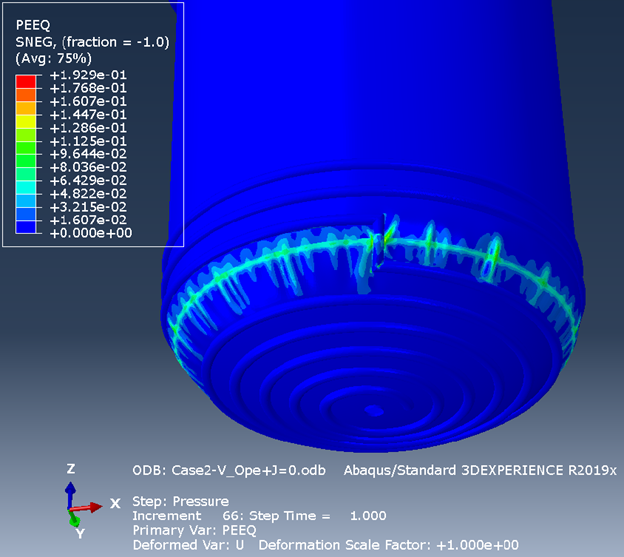
1. Main Problem Identified: A polymer storage tank’s bottom torispherical head was originally designed for very low uniform internal pressure (<1 psig) without explicitly accounting for the much higher hydrostatic head at the bottom, necessitating a combined-loading reassessment. The thin head’s knuckle region was expected to be buckling-susceptible under compression, making the head the limiting component.
2. Approach: Design-by-rule head checks (ASME VIII-1 Appendix 1-4) were used for screening only, recognizing they can be overly conservative for this geometry and that the attached half-pipe coil materially stiffens the head. A Design-by-Analysis was performed per ASME VIII-2 Part 5 using elastic-plastic FEA (ABAQUS), with factored vessel pressure and hydrostatic head (and, where applicable, jacket pressure) to evaluate plastic collapse and buckling. Multiple load cases were studied.
3. End Results: The unstiffened head did not satisfy code margins in plastic-collapse or buckling checks, whereas coil-stiffened cases converged and met the required design margins. Incorporating the half-pipe coil significantly increased head stiffness and pressure capacity, with the knuckle remaining the governing location under internal pressure. Thus, when evaluated by VIII-2 Part 5 methods under the governing combined-loading case, the head and shell were acceptable for the rating envelope.
-
Minimally Documented Drum Evaluation
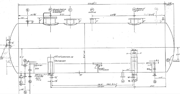
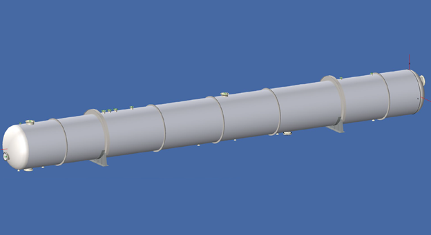
1. Main Problem Identified: Two large helium storage tanks needed to be qualified for higher internal pressure and a vacuum rating before being placed back into service. The key objective was to establish updated allowable ratings (MAWP/MAEP) using modern Code rules given limited legacy design documentation. Only a Form U-1 and nameplate were available.
2. Approach: The tanks were modeled in COMPRESS and evaluated per ASME VIII-1 using post-1999 allowable stresses; assessments focused on pressure loads only. As-built data from a field walk-down informed the model, and governing components for internal and external pressure were identified to determine controlling ratings; corrosion allowance was set to maximize allowable pressure in a non-corrosive service.
3. End Results: The evaluation established MAWP, MAEP, and MDMT. A hydrotest is required (greater than the original), after which formal rerating can proceed with no physical tank modifications.
-
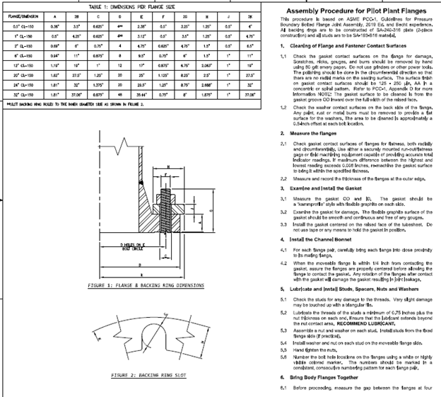
Bolted Flange Joint Procedure
1. Main Problem Identified: The project team needed a plant-wide, standardized process for bolted flange joint assembly to eliminate inconsistent practices in surface prep, gasket handling, bolt lubrication, and tightening methods. Without a single controlled procedure, the risk of startup leaks and rework across contractors remained unacceptably high.
2. Approach: A site-specific BFJ procedure was authored to define responsibilities, required materials, step-by-step assembly (clean/inspect, fit-up, multi-pass cross-pattern tightening, verification), tool calibration, and documentation requirements. The package included calculated target torque/tension tables by flange class and stud size, acceptance/hold criteria, troubleshooting guidance, and pre-/post-job QA/QC checklists for consistent execution from construction through commissioning. The document was issued as a controlled procedure for training and rollout.
3. End Results: The finalized procedure, torque tables, and sign-off forms provided a single, auditable method that improves bolt-load consistency and reduces the likelihood of leak-induced delays. The package was approved for site use and incorporated into contractor workflows to support reliable startups and repeatable maintenance.
-
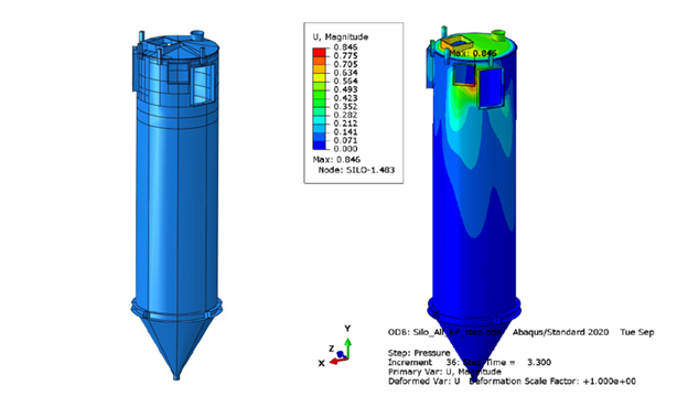
Silo Explosion Panel Opening Analysis
1. Main Problem Identified: New explosion-capacity requirements drove larger and/or additional explosion panels in two polymer silos, raising concerns about plastic collapse, buckling, and serviceability with the proposed rectangular openings. The plant also needed to know if added reinforcement (e.g., repads) was necessary and what weld detail could avoid interior scaffolding.
2. Approach: A design-by-analysis evaluation per ASME Section VIII, Division 2 Part 5 used nonlinear elastic–plastic FEA for plastic collapse and elastic bifurcation analysis for buckling, with acceptance based on achieving convergence at factored loads for API-620 construction and a serviceability limit. Models of both silos (no reinforcement added at openings) were analyzed at MAWP, assumed vacuum, and explosion conditions, and wind/seismic were screened as negligible compared to pressure.
3. End Results: Both silos met design and serviceability criteria without requiring reinforcement around the new/modified openings; max deformations and strains were acceptable. Buckling margins were ample and rotating the new opening was recommended to ease fit-up and reduce local stress; a single-sided bevel with fillet cap was proposed as the weld detail.
-
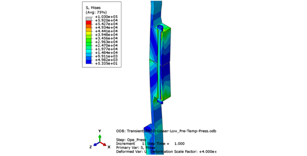
Reactor Main-Body Flange Assessment
1. Main Problem Identified: Historical leakage at the body flange pairs—exacerbated around a jet-fire event—raised concerns about flange integrity, bolt preload adequacy, and gasket seating during start-up/shutdown thermal transients. The previously applied bolt stresses were well below ASME PCC-1’s recommended values against yield, and the joint’s high gasket-to-bolt area ratio made reliable seating especially challenging.
2. Approach: The flanges were reassessed using ASME VIII-1 Appendix 2 design-by-rule, complemented by ASME VIII-2 design-by-analysis with WRC-538 stress limits and a detailed 3D FEA section model of the worst-case reactor, incorporating nonlinear gasket load/unload behavior. Both steady-state and transient thermal cases (normal start-up/shutdown, fire shutdown, and a 100 °F/hr ramp) were evaluated for gasket contact pressure, bolt stress versus PCC-1 70%-of-yield guidance, flange rotation, and hub/shell stress classifications. Modeling captured realistic boundary conditions, convection coefficients, preload variants, and internal pressure/thrust loads to identify governing behaviors.
3. End Results: The flange design demonstrated adequate mechanical integrity with no fundamental design deficiency; leakage susceptibility was attributed primarily to low assembly preload combined with the joint geometry. A 70%-of-yield preload achieved near-optimum average gasket seating while remaining acceptable for flange and bolt stresses, whereas the historical preload barely met minimum seating and allowed ID unloading at operating conditions. Transient checks indicated the joint could tolerate a modest thermal ramp structurally, but the OD of the gasket may crush under that scenario; the prior jet fire was not shown to have caused permanent flange damage.
-
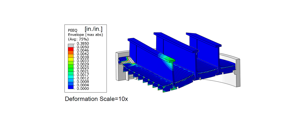
Reactor Bed dP Capacity Assessment
1. Main Problem Identified: Operational differential pressure (dP) at an intermediate catalyst bed was trending toward the historical design limit, prompting concern that the existing dP basis was inadequate for current conditions. The goal was to determine an upper-bound dP capacity for the corroded bed support while preserving an assumed design margin.
2. Approach: An API 579-1/ASME FFS-1 limit-load assessment with nonlinear FEA was performed, applying the global load combinations to demonstrate protection against collapse. A quarter-symmetry 3D model explicitly captured the shell segment, support ring and lugs, primary beams, grating, and braces; loads included catalyst deadweight and applied dP, with tie and contact interactions. Material properties were elastic-perfectly-plastic per ASME II-D at temperature, and convergence at the factored load defined capacity.
3. End Results: The bed met the required margin at an increased dP with global collapse in the inner beams governing; torsional buckling was screened as non-controlling. Recommendations included confirming remaining beam thickness and considering support modifications if still more capacity is needed.
-
PWHT Structural Stability Evaluation
1. Main Problem Identified: During local postweld heat treatment of a vertical reactor exchanger at approximately 1,175 ± 25 °F, reduced shell strength under heat plus wind and deadweight raised the risk of short-term (creep) buckling. The support legs would be limited to ≤900 °F, but confirmation was needed that both shell and legs would remain stable without temporary external supports via a crane during the PWHT.
2. Approach: A short-term buckling assessment was performed using API 579/ASME FFS-1 methods and inelastic/creep buckling approach, developing an isochronous stress–strain curve. Stresses from deadweight and a conservative wind load were calculated via a COMPRESS model and compared to allowable buckling stress; support legs were evaluated per AISC at 900 °F using interaction equations.
3. End Results: The compressive stress at the bottom of the PWHT band was well below the allowable buckling stress, with wind governing, so shell buckling during PWHT was not a concern. The legs satisfied AISC interaction checks and no supplemental supports were required for the heat treatment.
-

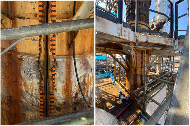
Nozzle Cracking Failure Assessment and Repair
1. Main Problem Identified: Cracking discovered at the weld between the inlet nozzle and shell of a stainless steel deaerator. Similar defects had been discovered at similar locations on other deaerators for the client.
2. Approach: Working with a metallurgical lab, destructive testing was performed to confirm the damage mechanism of the crack. Reviewed existing operating procedures and the physical characteristics of the inlet nozzle as well.
3. End Results: The damage mechanism was determined to be Caustic SCC from a combination of a poorly designed pH control system and non-standard hopper design. Redesigned the nozzle-hopper configuration to lower over-constraint and upgraded the local metallurgy since the pH control system was not readily modified.