
Mechanical Design and Analysis
-
Code-grounded designs your fabricator can build and your operators can trust. Refined Engineering develops complete, auditable calculation packages for refinery pressure equipment and piping—optimized for safety, reliability, and total installed cost.
What we deliver
Design basis & load cases: duty scenarios, MAWP/MDMT, corrosion/erosion allowances, wind/seismic, transportation/lifting, erection, hydrotest, vacuum/external pressure
Pressure vessels & columns: ASME VIII Div. 1/2, thickness and reinforcement, external pressure, nozzle/appendage checks (incl. WRC/API nozzle loads), saddles/skirts/lugs, flanges/gaskets, brittle-fracture/MDMT checks
Heat exchangers: ASME VIII (UHX) & TEMA; tubesheet/channel/shell design, expansion joint requirements, nozzle load compliance (API 660/661), mechanical–thermal integration and fouling allowances
Atmospheric & low-pressure tanks: API 650/620 design, shell courses, wind girders, anchorage/seismic (Annex E), roof/foundation interfaces, vents per API 2000
Piping systems: ASME B31.3/B31.1 wall thickness, branch reinforcement, flexibility/stress analysis, spring hangers/restraints, allowable nozzle loads at equipment interfaces
Materials & metallurgy: alloy selection, impact/hardness limits, PWHT criteria, sour service per NACE MR0175/ISO 15156
Relief & protection: PSV/vent sizing per API 520/521/2000 and required nameplate parameters
Shop-ready outputs: sealed (where required) calc reports, input summaries, design sketches/GA notes, nozzle load allowables, MTO assumptions, and a clean assumptions/change log
Quality & assurance
Independent check/peer review, code edition control, and traceable inputs from PFDs/P&IDs to final MDR
Use of industry-standard tools (e.g., PV design suites, piping stress solvers, and FEA for VIII-2 Part 5 where warranted)
Owner-ready outcomes
Verified compliance with ASME/API and project specs
Right-sized thicknesses and materials—lower weight, easier fabrication, safer operation
Faster vendor approvals and fewer RFIs/change orders
-
When Design-by-Rules is too conservative—or not enough—Refined Engineering applies Design-by-Analysis to demonstrate code compliance, optimize thickness, and resolve complex load paths in refinery pressure equipment.
Where it adds value
High nozzle loads, large openings, or tight d/t geometries
Thermal gradients/transients, cyclic duty, or startup/shutdown fatigue
Local details: skirts/lugs/saddles, head-to-shell knuckles, conical transitions, jackets, flanges/gaskets
Alternatives to over-thickening when DBA can justify leaner designs
What we do
Analysis plan & model QA: scope, idealizations, mesh strategy, boundary conditions, load mapping, material curves, and convergence checks
Elastic and elastic-plastic FEA with contact, nonlinearity, and stress linearization/categorization for primary/secondary loads
Code checks per VIII-2 Part 5: plastic collapse (limit-load), local failure, buckling, ratcheting (progressive deformation), and fatigue (cycle definitions & damage summation)
Thermal-structural coupling for steady/transient cases; assessment of PWHT/MDMT implications and weld detail hot-spots
Fitness-for-service integration when needed (e.g., use FEA results to support API 579 Level 3 evaluations)
Deliverables you receive
Sealed (where required) calculation report with acceptance summaries against VIII-2 criteria
Transparent inputs: load cases, cycles, material data, assumptions, and change log
Traceable outputs: plots, linearization paths, tabulated stresses, utilization ratios, and recommended design refinements
Exportable model snapshots and result files for your records/MDR
Owner-ready outcomes
Demonstrated ASME compliance for complex details—fewer RFIs and change orders
Right-sized designs (lower weight, easier fabrication) without sacrificing reliability
Longer fatigue life and clearer allowables for vendor and piping interfaces
-
Close the gaps between design and field execution. Refined Engineering delivers the “make-it-work” calculations that keep refinery projects safe, compliant, and install-ready.
What we deliver
Lifting & rigging: center-of-gravity and pick analysis; padeye/lug/sling/shackle/spreader sizing; local shell/attachment checks (FEA where warranted); lift plans and sketches per ASME B30/P30.1 and BTH-1.
Shipping & transport: over-the-road/rail/sea load cases, cribbing/grillage and sea-fastening design, skid/base ring checks, restraint layouts, and tie-down details aligned with DOT cargo-securement and applicable transport codes.
PWHT (Post Weld Heat Treatment): code basis and exemptions, P-Number driven soak times, ramp/soak/hold profiles, local vs. furnace PWHT, thermocouple placement, and documentation per ASME VIII/B31.3.
Pipe supports: sustained/thermal/occasional load combinations, spring/constant hanger selection, shoes/guides/stops/struts sizing, anchor and equipment nozzle allowables, details per MSS SP-58/69/89 and AISC.
Platforms, ladders & access: live/wind/seismic checks (ASCE 7/AISC), stair and ladder compliance (OSHA/IBC), guardrail and grating design, nozzle/valve/PSV reach envelopes, and GA/details for fabrication.
Package contents
Sealed (where required) calc reports, input summaries, and assumptions/change log
Marked GAs and detail sheets, bill of materials, and installation notes
Vendor coordination: allowable loads, interfaces, and hold/witness points for QA
Owner-ready outcomes
Safer lifts, smoother transports, and first-pass field acceptance
Documented compliance with ASME/API/OSHA and transport requirements
Fewer RFIs/change orders and faster mechanical completion
-
Independent, code-grounded assurance—plus a PE seal when required. Refined Engineering reviews designs for constructability, safety, and code conformance, then certifies documents in responsible charge to satisfy owner and jurisdictional needs.
What we review
Calculations per ASME VIII-1/2, ASME B31.3, API 650/620, API 660/661, and applicable project specs
Drawings & vendor submittals: GAs, nozzle orientation, internals, supports/lugs, platforms/ladders, foundations/interfaces
Loads & details: wind/seismic (ASCE 7), lifting/shipping cases, external pressure/vacuum, MDMT/brittle fracture, materials/PWHT
Relief & protection consistency: PSV/vent sizing (API 520/521/2000) aligned with design cases and datasheets
Fitness-for-service tie-ins when relevant (API 579 references)
Certification scope
PE-signed/sealed calculation reports, design summaries, and drawings produced by or reviewed under our responsible charge
Rerate/alteration/repair packages for existing equipment (coordination with API 510/570 programs and jurisdictional submittals)
Variance/State Special applications with technical justification and risk mitigations
Letters of compliance/conformance citing codes, editions, documents, and revision control
How we work
Independent check with comment log closure and traceable assumptions/change history
Coordination with the Owner, fabricator, and (where applicable) the Authorized Inspector and jurisdiction
Digital or wet seals per state rules; multi-state coverage available subject to registration and local requirements
Deliverables
Signed/sealed reports and drawings; transmittal index; basis-of-design summary; limitations & conditions of use
Audit-ready package for permitting, procurement, and turnover (MDR)
Owner-ready outcomes
Clear, defensible compliance with ASME/API and project standards
Faster approvals, fewer RFIs and change orders, and smoother fabrication/inspection
Documentation that stands up to internal, client, and regulatory review
Note: PE certification complements, but does not replace, manufacturer code stamping (e.g., ASME U/U2) and Authorized Inspector activities.
Sample Projects
-
Non-Standard Vessel Design
1. Main Problem Identified: Custom high-pressure vessel needed for rocket test instrumentation; client lacked in-house ASME vessel design experience. Stress and failure risk in custom radial bolting connecting the vessel to proprietary assembly.
2. Approach: ASME VIII-1 and VIII-2 design by rule and design by analysis assessments performed. A comprehensive elastic-plastic FEA for shell, head, skirt, and radial joint was created. Cyclic service, buckling, plastic collapse, and local failure modes evaluated.
3. End Results: Vessel design confirmed to be adequate for design conditions and pneumatic test. Bolt design validated for all loading scenarios at both design and test pressures. Recommended operating torque was provided to prevent over-torqueing by establishing torque limits for varying lubrication scenarios.
-
Design of Replacement Heat Exchangers
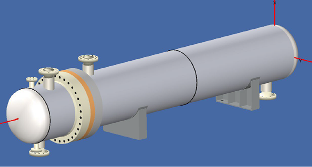
1. Main Problem Identified: Need to increase design pressure on the tube side of six identical, new exchangers beyond original design of old equipment.
2. Approach: Performed ASME Section VIII, Division 1 assessment using COMPRESS software. Completed review of shell and tube side MAWP and required thickness calculations. Tubesheet and nozzle re-evaluation was necessary for higher pressures.
3. End Results: Tube side successfully redesigned for increased design conditions on replacement exchangers. Only minor physical modifications required; gasket and bolt configuration was maintained. Supports operational flexibility with increased throughput.
-
Vessel Fatigue Redesign
1. Main Problem Identified: Repeated through-wall fatigue cracking in vessel heads after ~15 years of service (~500,000 cycles), leading to loss of containment.
2. Approach: Performed fatigue assessment per ASME VIII-2, Part 5 Design by Analysis. The critical stress areas were identified using FEA. From the initial results, the knuckle radius, support ring, nozzles, and manway were redesigned to improve fatigue life. Performed Fitness-for-Service tolerance checks via API-579.
3. End Results: The redesign extended the vessel life from 15 to 30 years and verified fatigue resistance at critical welds and nozzles. Delivered full drawing and specification set for new fabrication quotes.
-
Heavy Lift Analysis
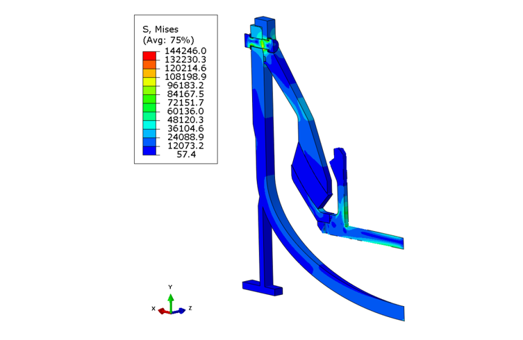
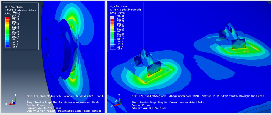
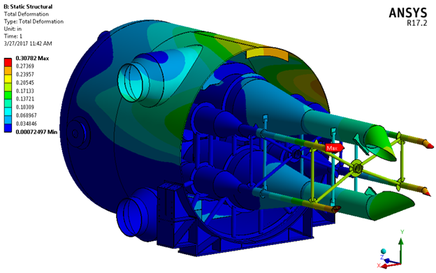
1. Main Problem Identified: Structural integrity of a pressure vessel weighing 600MT during erection lift using trunnions and lugs.
2. Approach: Nonlinear elastic-plastic and buckling FEA per ASME Section VIII-2. Evaluated weld strains, local collapse, and imperfection sensitivity using solid-shell hybrid modeling in ABAQUS.
3. End Results: Demonstrated sufficient margin against plastic collapse and against buckling. Concluded that plastic collapse governs the design and confirmed safe lifting without permanent deformation.
-

Heavy Equipment Shipping Calculations
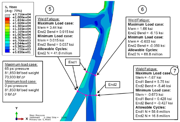
1. Main Problem Identified: Design and verification of saddle supports for a tall vertical vessel subjected to shipping loads.
2. Approach: Utilized Zick’s method for saddle stress evaluation. Load calculations for purge pressure, dead weight, wind, and dynamic excitation from shipment.
3. End Results: Saddle design confirmed adequate for all loading conditions. Maximum stresses for the saddles, the local vessel shell, and the shell between the saddels were within allowable limits. Structural integrity supported for safe field installation and long-term service.
-
Analysis of FCC Reactor Internals
1. Main Problem Identified: Structural evaluation needed for FCC Reactor cyclones and support bracing during transport and lifting.
2. Approach: Performed FEA-based stress and deflection assessment under closure seam welding, barge/road transport, and jacking scenarios. The design was checked per ASME Section VIII, Division 2 Part 5 and AISC stress limits. Load cases included transport G-loads and lifting reactions.
3. End Results: All cyclone dipleg and bracing components passed stress and deflection limits. Support configurations confirmed to be adequate for safe handling and transport of reactor internals.
-
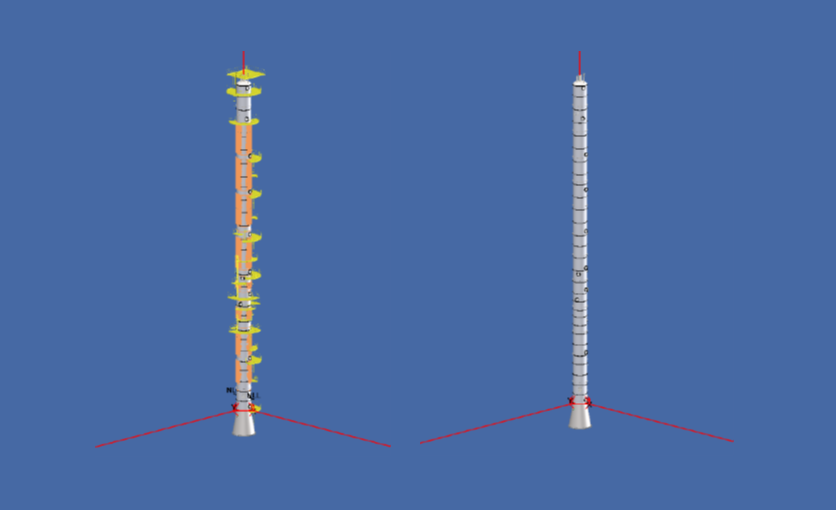
Tall Column Design Verification
1. Main Problem Identified: Design integrity review of a tall column under internal pressure, vacuum, and vortex shedding conditions.
2. Approach: ASME Section VIII-1 and VIII-2 review of shell thickness, nozzle reinforcement, flange ratings, and anchorage under both dead and seismic loads. Performed vortex shedding calcuatlons per industry standards to confirm critical wind speed at both operating and empty conditions.
3. End Results: Design verified to be code-compliant per ASME VIII-1. However, critical wind speed found to be susceptible for vortex shedding during empty conditions. Provided recommendations for mass dampeners and erection condition to prevent the column from hitting resonance.
-
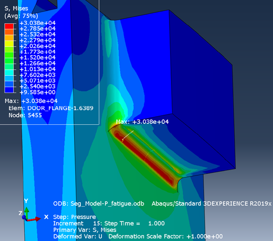
Autoclave Closure Analysis
1. Main Problem Identified: Need to certify a custom autoclave closure assembly for high-cycle service without standard ASME VIII-1 design rules.
2. Approach: Design-by-analysis per ASME VIII-2 Part 5 using 2D and 3D FEA in ABAQUS. Evaluated both primary stress limits and fatigue life under cyclic pressure and temperature loading.
3. End Results: Closure certified for the design conditions with a validated fatigue life of 60 years. Confirmed compliance with ASME Code, with recommendations for radiography and fatigue documentation under Mandatory Appendix 46.
-

FCC Regenerator Fit-Up Stand
1. Main Problem Identified: Design required for temporary erection frame during modular assembly of large FCC Regenerator head and cyclone assembly in the field.
2. Approach: Performed calculations using AISC design manual and STAAD.Pro. Load combinations for wind uplift, seismic lateral loads, and dead weight performed. Stability and deflection checks included bracing and connection designs.
3. End Results: Erection frame confirmed adequate for staging and field lifting. Welds and bolted connections sized appropriately. Report included layout drawings and member sizing for fabrication.