
Fitness-for-Service
-
Protect cold-weather and transient operations from brittle fracture. Refined Engineering performs Part 3 FFS assessments to establish defensible MDMT/MAT limits, define safe operating envelopes, and guide practical mitigations for refinery vessels, exchangers, piping, and tanks.
Where it applies
Carbon/low-alloy steels without impact testing or with unknown toughness
Non-PWHT weldments, thick sections, large discontinuities (nozzles, supports)
Winter startups, cold hydrotests, rapid pressurization/depressurization, cold soak risks
Nameplate MDMT questions after service changes or alterations
What we do
Data & basis: materials and weld maps, thickness/geometry, PWHT history, Charpy data (or justified proxies), load/stress cases.
Level 1 screening: quick MDMT check using controlling thickness, stress ratio, and code curves to flag risk.
Level 2 assessment: development of MAT vs. pressure/stress; explicit treatment of weld/HAZ, residual/thermal stresses, hydrotest and startup cases; set Minimum Pressurization Temperature (MPT).
Level 3 (as warranted): detailed stress extraction (including FEA) to refine stress ratios and local effects for tough-to-judge geometries.
Mitigation options we engineer
Operational: warm-up/soak procedures, ramp-rate limits, temporary heating/insulation, seasonal test plans, controlled depressurization.
Design/fabrication: targeted PWHT, impact-tested material substitutions, detail changes that reduce local stresses.
Deliverables
PE-sealed FFS report with acceptance basis per API 579 Part 3
MAT curves and safe-operation envelope charts; MPT/MAT tables for procedures and DCS limits
Clear operating and test recommendations; updates for MI files, datasheets, and turnover (MDR)
Owner-ready outcomes
Documented, auditable justification to operate safely at low temperature
Fewer unnecessary retrofits by using toughness-based limits instead of blanket conservatism
Faster winter startups and cleaner inspections with clear, field-friendly limits
-
General Thinning, Local Thinning (LTA) & Pitting
Turn wall-loss data into clear, defensible run/repair/replace decisions. Refined Engineering performs FFS assessments for vessels, exchangers, piping, and tanks to quantify remaining strength, MAWP, and remaining life—aligned with API 579 Parts 4, 5, and 6.
Where it applies
Corrosion/erosion in shells, heads, nozzles, branches, and tank courses
Localized thinning near discontinuities (saddles, skirts, repads, weld toes)
Pitting—isolated or widespread—affecting integrity or setpoints
Post-inspection evaluation to set next inspection intervals (NII)
What we do
Data & screening: QC of UT grids/scans, pit maps, radiography; define corrosion circuits and damage morphology.
Part 4 – General metal loss: calculate tmint_{min}tmin, RSF/MAWP, remaining life with corrosion-rate trending; set operating limits.
Part 5 – Local metal loss (LTA): profile-based evaluation of critical areas (including nozzles/branches) with allowable dimensions, reinforcement checks, and optional FEA for complex geometry.
Part 6 – Pitting: method selection based on pit density/depth distribution; evaluate pitting factor, remaining strength, and implications for leak-before-break and setpoints.
Integration: revalidate relief requirements (API 520/521/2000) when MAWP changes; align with API 510/570/653 program needs.
Recommendations: targeted mitigations (operational limits, monitoring, coating/CI guidance) and clear triggers for re-assessment.
Deliverables
PE-sealed FFS report citing Parts 4–6 acceptance criteria
RSF and MAWP tables, controlling locations, and utilization ratios
Remaining life & NII recommendations with corrosion-rate basis
Annotated UT/pit maps, CAD overlays of critical profiles, and assumptions/change log
Updates for datasheets, asset registry, and turnover (MDR)
Owner-ready outcomes
Auditable justification for continued service at defined limits
Focused maintenance and inspection plans—fewer unnecessary repairs
Clear communication to operations, inspection, and reliability teams
-
Turn shape deviations into clear run/monitor/repair decisions. Refined Engineering evaluates misalignment and distortion in refinery vessels, exchangers, piping, and tanks—quantifying risk and defining safe operating envelopes per Part 8.
Where it applies
Shell/course ovality (out-of-roundness), peaking/flat spots, dents/buckles/wrinkles
Weld misalignment (hi-lo/angular) at long. & circumferential seams; nozzle distortion/out-of-plumb
Supports/saddles/cone-to-cylinder transitions; transport/lift/set-down damage
External pressure/vacuum vulnerability and startup/shutdown transients
What we do
Survey & QC: laser scan/templating/tape checks; establish baselines and tolerances; data sanity review
Characterization: compute ovality %, peaking h/th/th/t, dent depth/extent ratios, eccentricities, and offsets at welds/nozzles
Part 8 assessment: screening and detailed checks for local membrane/bending effects, collapse/buckling under vacuum/external loads, and interaction with internal pressure
Coupled effects (as needed): integrate Parts 3 (brittle fracture) and 4–6 (metal loss) where geometry and thinning interact
Advanced analysis: targeted FEA for complex details to refine stresses, utilization, and allowable limits
Mitigations: engineered re-rounding/pressurization bounds, mechanical jacking plans, heat-straightening guidance, local reinforcement/stiffeners, and operating/vacuum limits
Deliverables
PE-sealed FFS report citing Part 8 acceptance criteria and utilization ratios
Annotated geometry maps/profiles (ovality, dents, misalignment) with controlling locations
Safe-operation recommendations (pressure/vacuum limits, monitoring triggers) and optional re-rounding/straightening procedures
Updates for datasheets/asset registry and turnover (MDR) with traceable assumptions/change log
Owner-ready outcomes
Auditable justification to continue service at defined limits
Reduced buckling and leak risk during vacuum, startup, and transport events
Focused work scopes, fewer RFIs, and clearer decisions for inspection and maintenance
-
Turn impact damage into clear, defensible decisions. Refined Engineering assesses dents, gouges, and combined dent-gouge damage in refinery vessels, exchangers, piping, and tanks—setting safe operating limits and defining practical next steps per Part 12.
Where it applies
Handling/transport or in-service impacts: cranes, rigging, dropped objects, line-of-fire events
Thin-wall shells and piping susceptible to local collapse or stress concentration
Damage near welds/nozzles, supports, or cold regions where brittle fracture could co-govern
What we do
Data & QC: laser/templated geometry for dent depth/span/curvature; UT thickness and profiling; high-fidelity surface scans for gouge depth/shape; MT/PT for crack screening.
Part 12 evaluation: calculate governing dent ratios (depth/diameter or depth/width), local curvature/strain, and gouge severity; check interaction rules for combined damage and proximity to welds/discontinuities.
Load integration: evaluate internal pressure, vacuum/external pressure, thermal/cycle effects, and startup/shutdown transients; consider vibration and pulsation where relevant.
Coupled assessments (as needed): integrate Part 3 (brittle fracture) and Parts 4–6 (metal loss) when thinning or low-temperature limits interact with the dent/gouge response.
Advanced analysis: targeted FEA to resolve local membrane/bending strains, stress concentration factors, and allowable envelopes when geometry is complex.
Mitigations we can engineer
Operate/monitor with defined pressure/vacuum and temperature bounds
Precision blending to remove sharp gouge notches while preserving required thickness
Local mechanical re-rounding/jacking procedures and inspection checkpoints
Design tweaks (guards/stiffeners) to reduce recurrence risk; repair concepts provided separately if chosen
Deliverables
PE-sealed FFS report citing Part 12 acceptance criteria and controlling locations
Utilization tables and go/monitor/mitigate recommendations with inspection intervals
Annotated geometry/thickness maps, assumptions/change log, and updates for MI files/MDR
Owner-ready outcomes
Auditable justification to continue service or mitigate safely
Reduced leak/collapse risk and fewer unnecessary repairs
Clear guidance for operations, inspection, and reliability teams
-
Turn hydrogen damage into clear run/monitor/repair decisions. Refined Engineering performs Part 7 assessments to quantify risk from blisters, HIC, and SOHIC and define safe operating envelopes for refinery vessels, exchangers, piping, and tanks.
Where it applies
Sour service (elevated H₂S partial pressure) in carbon/low-alloy steels
Plate/HAZ regions showing laminations, stepwise cracking, or stacked cracking arrays
Damage near welds, nozzles, or high-stress areas that could threaten ligaments or leak integrity
What we do
Data & screening: service chemistry and H₂S pp, materials/PWHT history, hardness, UT thickness maps, A-/B-scan, PAUT/TOFD, MT/PT for surface connection, blister/HIC mapping.
Level 1: quick acceptance using size, spacing, and remaining ligament checks; proximity to welds/discontinuities.
Level 2: detailed ligament-efficiency/MAWP evaluation, interaction of multiple features, local stress effects, and set operating limits.
Level 3 (as warranted): fracture-mechanics/FEA-informed stresses for complex geometry, weld HAZ, or interacting flaws.
Integration: coordinate with Part 3 (brittle fracture) where toughness/MDMT may co-govern; update relief/device basis if MAWP is revised; align with API 510/570 program needs.
Mitigations we can engineer
Operating limits (pressure/temperature), monitoring plans, and re-inspection intervals
Targeted hardness/toughness controls, material upgrades (HIC-resistant steels), internal liners/cladding concepts, and stress-reduction measures
Repair concepts provided separately if selected (design and execution not included here)
Deliverables
PE-sealed FFS report citing Part 7 criteria and controlling locations
MAWP/RSF tables, safe-operation envelopes, and go/monitor actions
Annotated damage maps, assumptions/change log, and updates for MI files/MDR
Owner-ready outcomes
Auditable justification to continue service at defined limits
Focused mitigations and inspection—fewer unnecessary replacements
Clear guidance for operations, inspection, and reliability teams
-
Protect high-temperature assets from time-dependent damage. Refined Engineering performs Part 10 assessments to quantify creep damage, remaining life, and safe operating limits for refinery vessels, heaters/coils, hot piping, headers, and reactors.
Where it applies
Long-term service in the creep range (e.g., Cr-Mo steels, austenitics)
Weldments/HAZ (Type IV risk), thick sections, hot manifolds and bends
Units with temperature excursions, coke/scale buildup, or uneven heat flux
What we do
Data & basis: materials/PWHT history, weld maps, operating temps/pressures and time-at-temperature, excursions, thickness trends.
Targeted NDE: dimensional surveys for bulging/ovality, hardness mapping, in-situ replication (metallography), PAUT/TOFD for creep cracking, UT thickness profiling, MT/PT for surface connection.
Level 1 screening: time-fraction (Robinson) damage check versus allowable rupture data to flag concerns.
Level 2 assessment: refined metal-temperature mapping (thermography/spot TCs/oxide-thickness correlation), local stresses, weld/HAZ evaluation, MAWP at temperature, remaining life and next inspection interval.
Level 3 (as warranted): inelastic/creep FEA (e.g., Norton-Bailey/omega-type models) for complex geometries, hot spots, or interaction with pressure/secondary loads.
Integration: consider creep–fatigue interaction (link to Part 14 when cycling is significant) and update relief/device bases if MAWP changes.
Mitigations we can engineer
Operating derates, temperature balancing, start-up/soak controls, monitoring plans
Material upgrades or weld detail changes in future turnarounds; local reinforcement concepts (if selected separately)
Deliverables
PE-sealed FFS report citing Part 10 acceptance basis
Damage consumption/RSF tables, remaining life, and decision matrix (run/monitor/mitigate)
Hot-spot maps, inspection intervals, and condition-monitoring recommendations
Updates for MI files, datasheets, and turnover (MDR) with clear assumptions/change log
Owner-ready outcomes
Auditable justification to continue service at defined limits
Fewer unplanned outages through focused monitoring and targeted mitigations
Clear guidance for operations, inspection, and reliability teams
-
Quantify cyclic damage and run with confidence. Refined Engineering performs Part 14 fatigue assessments to establish remaining life, allowable cycles, and safe operating envelopes for refinery vessels, exchangers, piping, and tanks.
Where it applies
Thermal cycling (startups/steam-outs, quench, rapid ramping)
Pressure/flow cycling, relief chatter, control-valve pulsation, rotating equipment tie-ins
Welded details at nozzles, supports, skirts, saddles, and branch connections
What we do
Data & basis: duty cycle definition from DCS/ historian data, transient profiles, materials/PWHT, weld details, thickness, and geometry.
Cycle counting: rainflow/block counting to convert time histories into stress/temperature cycles; duty matrices for startups, trips, and normal ops.
Stress evaluation: primary/secondary stress ranges with stress concentration factors (SCFs) and fatigue strength reduction factors (FSRFs); hot-spot or linearized stresses via targeted FEA where warranted (VIII-2 Part 5 methods).
Assessment levels:
Level 1 simplified screening against code curves to flag risk.
Level 2 detailed S–N evaluation with mean-stress and weld-detail effects; Miner’s Rule damage summation and remaining life.
Level 3 advanced analysis (FEA/fracture mechanics) for complex geometries or interacting loads.
Integration: consider corrosion- or creep–fatigue interaction (tie-in to Parts 4–6 and Part 10) when environment or temperature regime co-govern.
Mitigations we can engineer
Operating changes: ramp-rate limits, soak/hold strategies, setpoint tuning, pulsation/damping control
Design tweaks: flexibility at connections, nozzle/load redistribution, support/hanger adjustments, weld toe dressing/peening, local reinforcement
Monitoring: targeted vibration/temperature/pressure instrumentation and re-inspection intervals
Deliverables
PE-sealed FFS report citing Part 14 acceptance basis
Allowable-cycle and utilization tables by transient; remaining life with confidence bounds
Controlling locations, stress/SCF documentation, and recommended operating envelopes
Inspection/monitoring plan and updates for MI files and turnover (MDR)
Owner-ready outcomes
Auditable justification to continue service at defined limits
Fewer fatigue failures and unplanned outages through targeted controls
Clear guidance that aligns operations, inspection, and reliability teams
-
Turn indications into clear, defensible run/monitor/repair decisions. Refined Engineering applies fracture-mechanics assessments to surface and embedded cracks in refinery vessels, exchangers, piping, and tanks—so you know the real risk and the safe operating envelope.
Where it applies
Weld/HAZ and heat-affected regions at shells, heads, nozzles/repads, skirts, saddles, and branch connections
Indications from MT/PT/UT/PAUT/TOFD (e.g., toe cracks, lack-of-fusion, thermal/mechanical fatigue)
Startup/shutdown thermal cycling, high nozzle loads, vibration/pulsation, or cold service near MDMT
What we do
Characterization & QC: validate NDE technique/sizing, orientation (long./circ.), flaw geometry (length/depth/ellipticity), proximity to discontinuities, and remaining ligament.
Loads & stresses: establish primary/secondary loads (pressure, thermal gradients, residual weld stress, external/nozzle loads); extract local stresses (hand calcs or targeted FEA).
Part 9 assessment: evaluate fracture and plastic collapse using FAD methods (Levels 1–3); compute KIK_IKI, KmatK_{mat}Kmat (from CVN correlation or test data), and LrL_rLr acceptance; check MDMT sensitivity.
Crack growth forecasting: fatigue life via cycle counting (ΔK/Paris law), corrosion-fatigue/environmental effects where applicable; set inspection intervals and allowable cycles.
Integration: coordinate with Part 3 (brittle fracture) for low-temperature risk and Part 14 (fatigue) for duty-cycle realism; update relief/MAWP basis if needed.
Mitigations (engineering concepts): blend/grind & re-inspect, local PWHT/residual-stress relief where permitted, geometry/detail tweaks, operating envelope/ramp-rate limits; repair design provided separately if selected.
Deliverables
PE-sealed FFS report citing Part 9 criteria with pass/monitor/repair recommendations
Utilization tables (K_r, L_r), critical crack sizes, remaining-life/inspection interval tables, and allowable operating envelopes
Annotated NDE maps, assumptions/change log, and updates for MI/MDR files
Owner-ready outcomes
Auditable justification for continued service at defined limits
Focused inspections and targeted mitigations—fewer unnecessary outages
Clear guidance that aligns operations, inspection, reliability, and vendors
-
Turn planar plate defects into clear run/monitor/repair decisions. Refined Engineering performs Part 13 assessments to quantify the integrity impact of laminations and delaminations in refinery vessels, exchangers, piping, and tanks—so you know what can safely stay in service.
Where it applies
Rolled plate shells/heads, nozzle pads/reinforcement zones, cones and transitions
Areas near welds, supports, and openings where through-thickness strains are high
Indications revealed by UT/PAUT/TOFD as mid-wall reflectors or layered separations
What we do
Data & QC: UT mapping (A-scan/PAUT/TOFD), thickness and geometry, orientation/size/depth of laminations, proximity to welds/nozzles, service conditions and loads.
Level 1 screening: quick acceptance checks based on indication dimensions vs. thickness and distance from discontinuities.
Level 2 assessment: remaining-ligament/MAWP evaluation, stress-path bypassing, interaction with openings/nozzles, and allowable operating limits.
Level 3 (as warranted): targeted FEA to resolve local membrane/bending stresses and utilization where geometry or multiple laminations interact.
Integration: consider co-governing limits from brittle fracture (Part 3) or metal loss (Parts 4–6) if applicable; update relief basis if MAWP changes.
Mitigations we can engineer
Operating bounds and monitoring intervals for safe continued service
Layout/design adjustments (e.g., relocate openings, resize pads) to keep high-strain zones off laminated areas
Material/QA guidance for future work (e.g., Z-quality plate, enhanced UT acceptance)
Repair concepts provided separately if selected
Deliverables
PE-sealed FFS report citing Part 13 acceptance criteria
MAWP/RSF tables, controlling locations, and go/monitor actions
Annotated UT maps and profiles, assumptions/change log, and MI/MDR updates
Owner-ready outcomes
Auditable justification to operate at defined limits
Focused mitigations and smarter inspection—avoiding unnecessary replacements
Clear guidance that aligns operations, inspection, and reliability teams
-
Determine what can safely return to service after a fire. Refined Engineering performs Part 11 assessments to quantify heat exposure, evaluate property loss, and set clear run/monitor/repair decisions for refinery vessels, exchangers, piping, and tanks.
Where it applies
Units exposed to external fire or hot vapor impingement (localized or widespread)
Insulated/painted equipment with possible hidden heat soak, skirts/saddles with thermal distortion
Attachments and internals (nozzles, repads, trays, supports) and connected piping
What we do
Scene reconstruction: exposure duration/intensity from incident logs, insulation/metal discoloration, oxide-scale thickness, and temperature markers to estimate peak metal temps.
NDE & measurements: visual/laser surveys for bulging/ovality; UT/PAUT/TOFD for wall/lamination; hardness mapping; in-situ metallographic replication; PMI; spot Charpy where feasible.
Part 11 evaluation: screening vs. critical temperature thresholds; detailed checks using reduced material properties (strength/toughness) for affected zones; weld/HAZ sensitivity and bolting effects; reassessment of MAWP and MDMT.
Interaction with other damage modes: integrate Part 3 (brittle fracture) for low-temp restarts, Parts 4–6 (metal loss) for scale/oxidation thinning, and Part 8 (distortion) for buckling under vacuum/external loads.
System readiness: relief devices, gaskets, elastomers, instruments, coatings/insulation—identify what must be replaced or recalibrated before restart.
Mitigations we can engineer
Local or full PWHT/normalizing/solution anneal plans where heat treatment restores properties
Re-rounding/straightening procedures and stiffness upgrades if distortion governs
Operating envelopes (pressure/temperature/ramp rates) for monitored service and phased restart
Targeted replacements (bolting, gaskets, PSV internals, affected spools) with clear scope limits
Deliverables
PE-sealed FFS report citing Part 11 acceptance basis and controlling locations
Heat-affected zone maps, property/MAWP/MDMT updates, and go/monitor/repair recommendations
NDE/pressure test plans, acceptance criteria, and post-event baseline records for MI files (MDR updates)
Clear assumptions/change log and required hold/witness points for verification
Owner-ready outcomes
Defensible, auditable decision on restart vs. repair/replacement
Reduced risk of brittle fracture, leaks, or buckling on return to service
Focused work scopes and faster, safer commissioning after a fire event
Sample Projects
-
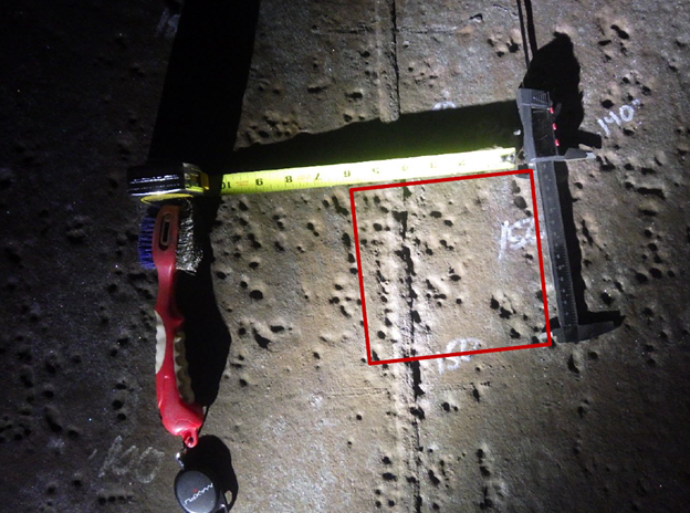
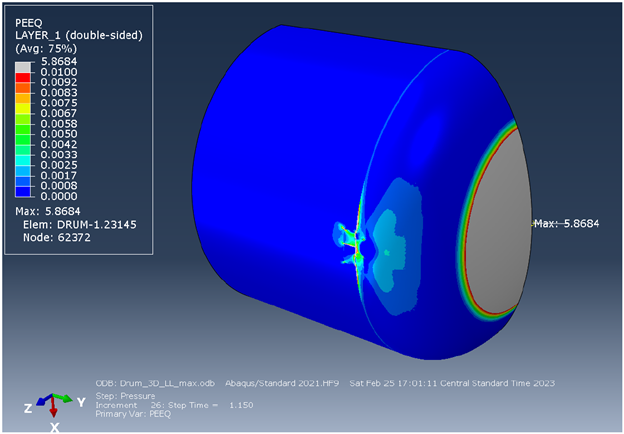
Spheroid Vessel Part 6 Pitting FFS Assessment
1. Main Problem Identified: Inspection identified widespread pitting up to 0.160 inch concentrated in the lower shell of a large spheroidal storage vessel. A Part 6 fitness-for-service evaluation was initiated to determine minimum required shell thicknesses and available corrosion allowance while maintaining original Code design margin.
2. Approach: A Level 3 API 579-1/ASME FFS-1 assessment employed a limit-load methodology with nonlinear FEA and RSFa = 1.0 to preserve the construction Code design margin. A 3D partial-symmetry model captured the shell, girder supports, and base plate; loads included internal pressure, static liquid head, and deadweight with joint efficiency E = 0.8. Minimum required thicknesses were identified by iteratively reducing plate thickness until convergence at the mandated design factor, with Part 6 pitting checks available if corrosion exceeded the Part 4 allowance.
3. End Results: The spheroid vessel satisfied the required margin with a sufficient collapse load factor and the calculated minimum required thicknesses yielded future corrosion allowances for continued operation. Because the maximum measured pit depth (0.160 in) is less than the lower-section corrosion allowance, the component was deemed fit for service with no mechanical repairs. Recommendations included treating 0.100 in as the structural minimum for the lower shell to prevent pinhole leakage, repairing any future pits beyond that, and confirming the sand support remains in good condition to maintain conservatism.
-
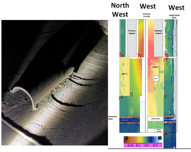
Reboiler Part 5 LTA & Part 9 Crack FFS Assessment
1. Main Problem Identified: Inspection found crack-like indications on the outer shell near the head-to-shell weld of a recycle-service vessel; attempts to grind out the defects were unsuccessful, leaving several small flaws within locally thinned cavities. The evidence pointed to stress corrosion cracking driven by chlorides in insulation or fluoride exposure, and the weld discontinuity at the head junction meant a higher-rigor assessment was warranted.
2. Approach: A Level 3 fitness-for-service evaluation per API 579/ASME FFS-1 was performed, modeling the local thinned areas with a nonlinear limit-load analysis and developing a through-wall stress profile for crack assessment. Crack stability was checked using Part 9 Failure Assessment Diagram methods with conservative assumptions (infinite-length surface crack at measured depth, residual weld stresses), while Part 5 addressed the LTAs under design pressure loading with appropriate symmetry constraints.
3. End Results: Both the LTA and crack assessments were acceptable for continued service: the limit-load model showed margin and the crack assessment points plotted below the FAD acceptance curve. To manage the SCC mechanism and risk, recommendations included applying a removable external barrier, initiating close post-startup monitoring (about monthly initially), and recognizing that with 316SS toughness any progression would likely present as leakage rather than catastrophic fracture; longer-term run/replace decisions were tied to risk tolerance.
-
Amine Stripper Part 5 LTA FFS Assessment
1. Main Problem Identified: Local thin areas were discovered on the second bottom shell course of an amine stripper vessel, prompting a fitness-for-service evaluation. The assessment considered the design condition and included site loads, while external pressure was excluded via administrative controls.
2. Approach: A Part 5 Level 3 assessment per API 579 used elastic-plastic analysis requiring convergence at an effective load factor of 3.6 for plastic-collapse acceptance; buckling was evaluated by ASME VIII-2 Method B using an eigenvalue-derived imperfection equal to 1% of vessel diameter with a stability target of ≥ 1.67. Global loads were calculated in COMPRESS and applied to a bottom-section FE model that incorporated measured thickness mapping and corrosion allowances. The load set included pressure thrust, deadweight, wind shear/bending, and platform clip loads.
3. End Results: The vessel satisfied the acceptance criteria—plastic-collapse cases and buckling analysis achieved acceptable load factors. The evaluation found the component acceptable with RSF = 0.9 and a 1/16-in future corrosion allowance at the LTA, recommended re-inspection in six months, and treated external pressure by administrative control rather than calculation.
-
Condenser Head Part 12 Dent FFS Assessment
1. Main Problem Identified: During repair work on a surface condenser, inspection found a localized dent in the elliptical head knuckle measuring approximately 3 in × 1 in × 0.25 in. Because knuckle stresses are complex, the condition could not be screened by Level 1/2 and required a Level 3 fitness-for-service assessment.
2. Approach: The evaluation followed API 579-1 Part 12 using elastic-plastic finite element analysis; a 3D quarter-symmetry ABAQUS model with a rigid “indenter” recreated the dent, then internal pressure was applied to the deformed geometry. Material nonlinearity and local thickness minus corrosion allowance were modeled as required, and only internal pressure governed based on location and support conditions. The Section VIII-1 design margin was applied setting an achieveable acceptance target for stability/convergence.
3. End Results: The model converged under the factored load cases and demonstrated protection against plastic collapse, confirming the dented head is fit for continued service; the deformed-shape check showed residual dent depth versus the field measurement, providing conservatism. Recommendations were to perform close inspection of the dent area for cracking from the original impact but otherwise no special ongoing inspection was deemed necessary.
-
Heater Baffle Part 10 Creep Analysis
1. Main Problem Identified: An internal heater baffle in long-term service exhibited critical overstress at hanger-attachment regions, with local stresses approaching roughly twice typical allowable values for non-pressure components—indicating a fundamental design deficiency rather than simple time-dependent degradation. The condition created a credible drop hazard in which failure of one or more hangers could allow the baffle to fall into the firebox; historical temperature and inspection cues (e.g., ~950 °F flue-gas conditions and observed top-plate deformation) supported the concern.
2. Approach: A three-dimensional finite-element model (shell + beam) was built to locate and quantify stress hot spots and to reflect the actual attachment details and support conditions; this structural analysis was paired with a long-term creep evaluation. Because creep constants for the vintage 309S alloy were unavailable, the assessment followed API 579-1 Part 10 at 950 °F for 500,000 h using bounding properties for 304 and 316 stainless steels to frame realistic life-consumption extremes.
3. End Results: Stresses at the hanger-attachment regions governed, while other locations remained acceptable—confirming the local nature of the deficiency and the associated drop consequence. Bounding creep results indicated life could be exhausted at the attachments in a lower-strength scenario but ~60% consumed with higher-strength data, steering recommendations toward prompt inspection and reinforcement rather than temperature increases. Recommended actions included immediate visual/PT examination of all hanger connections and stiffener welds, verification of bolting, and reinforcement of the hanger locations regardless of findings; as a more permanent risk-removal option, eliminating the baffle was also considered.
-
PWHT Creep-Buckling Assessment
1. Main Problem Identified: During local postweld heat treatment of a vertical reactor exchanger at approximately 1,175 ± 25 °F, reduced shell strength under heat plus wind and deadweight raised the risk of short-term (creep) buckling. The support legs would be limited to ≤900 °F, but confirmation was needed that both shell and legs would remain stable without temporary external supports via a crane during the PWHT.
2. Approach: A short-term buckling assessment was performed using API 579/ASME FFS-1 methods and inelastic/creep buckling approach, developing an isochronous stress–strain curve. Stresses from deadweight and a conservative wind load were calculated via a COMPRESS model and compared to allowable buckling stress; support legs were evaluated per AISC at 900 °F using interaction equations.
3. End Results: The compressive stress at the bottom of the PWHT band was well below the allowable buckling stress, with wind governing, so shell buckling during PWHT was not a concern. The legs satisfied AISC interaction checks and no supplemental supports were required for the heat treatment.
-
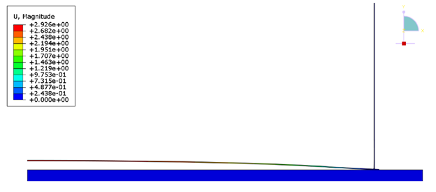
Tank Vacuum Assessment
1. Main Problem Identified: The tank had been rerated to withstand −18 in. WC external pressure, but API calculations indicated a minimum liquid level would be needed to prevent the bottom from lifting. Operations indicated that the tank could see full vacuum with the tank empty. The question was whether an empty-tank vacuum case would overstress the shell-to-bottom junction or bottom lap welds.
2. Approach: An elastic finite-element analysis with geometric nonlinearity (Abaqus) was performed on an axisymmetric model of the shell, bottom, and foundation, using contact to allow realistic bottom uplift and applying gravity then the −18 in. WC vacuum. Stresses were linearized along classification lines and checked to API-653 and API 579-1/ASME FFS-1 criteria.
3. End Results: The model predicted ~3.0 inches of upward deflection at the bottom center under full vacuum, but all membrane and membrane-plus-bending stresses in the shell and bottom remained within allowable limits with margins, including the lap-weld shear check. Operation at −18 in. WC with no liquid in the tank was therefore acceptable.
-
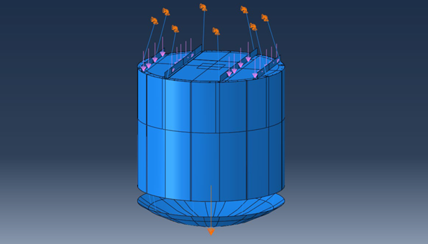
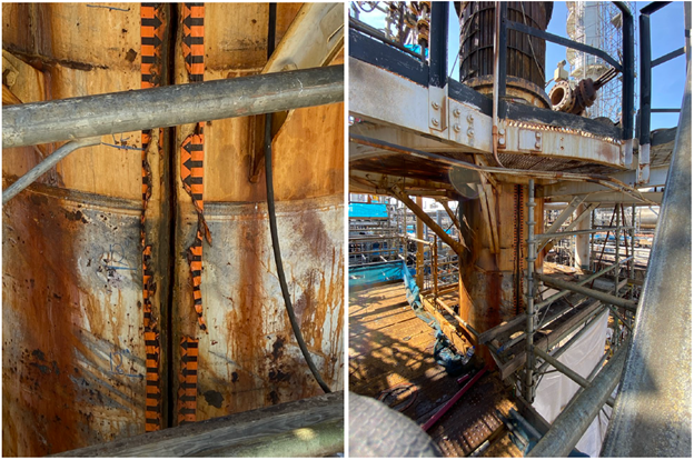
Heater Piping Vibration Assessment
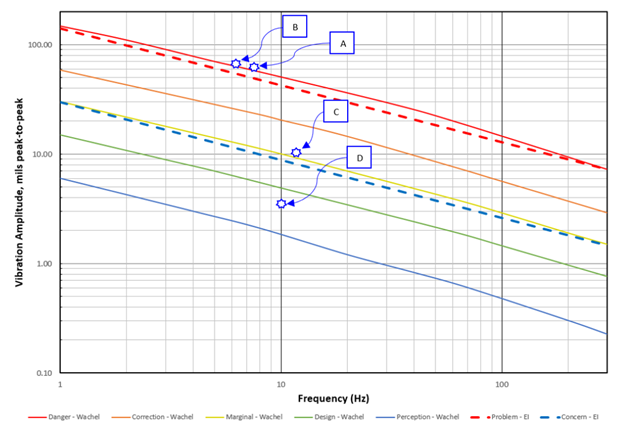
1. Main Problem Identified: During capacity testing, visible piping vibration emerged as flow increased through a charge heater; even at baseline operation the measured responses warranted reduction for long-term service. At the ramped condition, locations at the inlet flange and crossover reached the “Problem/Danger” region on accepted criteria, confirming the need for corrective action prior to sustained higher-rate operation..
2. Approach: Vibration severity was evaluated against two industry criteria—the Wachel curves and the UK Energy Institute guideline—while converting measurements between displacement and velocity domains for consistent comparison. Data were collected at four representative locations using an accelerometer, then reduced to peak velocities and peak-to-peak displacements with resultants computed for evaluation.
3. End Results: The assessment identified two-phase slug flow of mixed process liquid and hydrogen as the primary excitation mechanism, and recommended either process changes to reduce slugging or structural mitigation to attenuate response. Specifically, long-term modifications are advised for operation above normal rates and should be implemented before running at the increased rates, with conceptual spring-damper supports detailed for the inlet and crossover lines.
-
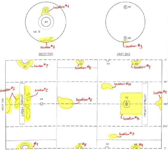
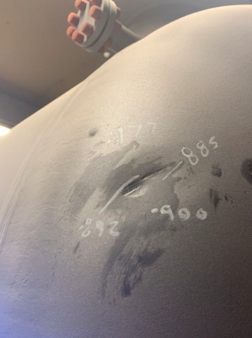
Surge Vessel Part 4 GML FFS Assessment
1. Main Problem Identified: External inspection found corrosion under insulation and pitting in about fifteen regions of the shell. Confirmation was required that the vessel could safely remain in service at its design conditions.
2. Approach: A Level 2 fitness-for-service evaluation per Part 4 General Metal Loss of API 579/ASME FFS-1 was performed with a RSFa = 0.9 by conservatively applying the lowest measured remaining thickness to the overall shell. This approach was desired by the client to provide a conservative remaining life.
3. End Results: The conservative remaining thickness demonstrated adequate remaining life for the vessel until the replacement drum was to be installed several months later. The uniform-thickness study set an acceptable minimum wall and recommendations included periodic inspection to ensure wall thickness and no individual pit deeper than a specified depth from nominal.