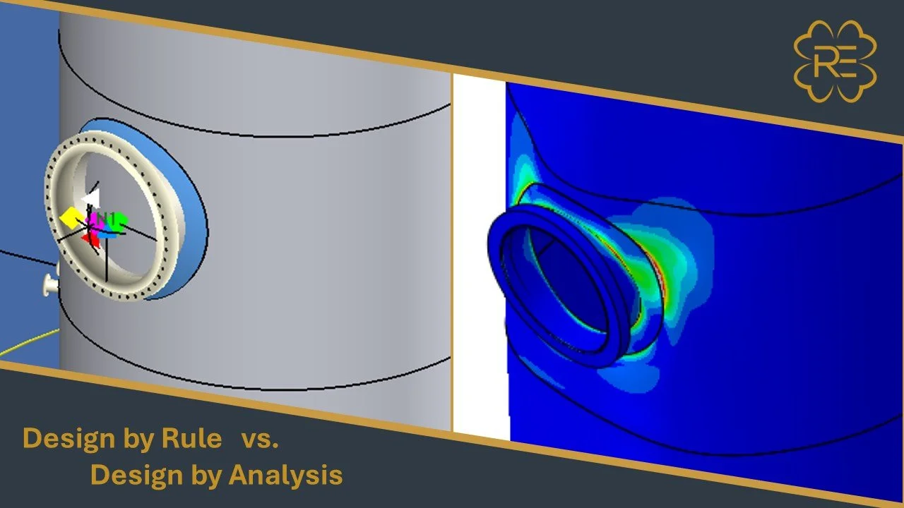
Use Design by Rule when the vessel fits the code’s prescriptive requirements. Use Design by Analysis when geometry, loading, or service conditions need a more detailed demonstration. The practical choice is not “simple engineering versus sophisticated engineering.” It is whether the applicable design rules adequately represent the design problem, and whether additional analysis will support a better, defensible decision.
For owners, fabricators, and engineering firms, that decision affects more than calculation hours. It can change vessel weight, fabrication and examination requirements, documentation, rerate feasibility, and the confidence available for operating limits.
First, clarify what “Design by Analysis” means
ASME Section VIII, Division 1 is commonly associated with Design by Rule (DBR): prescriptive requirements for pressure-boundary thickness, openings, materials, fabrication, examination, and testing. For a conventional vessel within those requirements, it is often the most direct and economical design path.
Division 2 is not synonymous with Design by Analysis as some suppose. It includes both Part 4, Design by Rule provisions and Part 5, Design by Analysis. Part 5 provides a structured way to assess applicable failure modes using numerical methods such as finite element analysis. The selected division and code edition must match the project’s construction and certification basis. If you’re looking for a more in-depth breakdown of the rules of both Division 1 and/or Division 2, contact me at nathan@refinedengineering.com to setup a training session.
When Division 1 Design by Rules is the right path
Division 1 is generally appropriate when the vessel has conventional geometry, materials and service conditions; its pressure-boundary components fit the applicable rules; and the required checks can be completed without relying on a detailed stress analysis to establish acceptability.
Typical examples include standard shells, heads, and openings where the applicable thickness and reinforcement rules address the design, and where loads can be evaluated using established code methods. The engineer still needs a complete design basis: operating and design conditions, material properties, corrosion allowance, joint efficiency, external loads, support conditions, and relevant test or transport cases.
For openings, Division 1’s familiar area-replacement approach, principally UG-37 and related paragraphs, checks whether sufficient reinforcement area is available around the opening. Alternately, the more modern rules of Division 2, Part 4.5 can be used for Division 1 construction through UG-16 and Mandatory Appendix 6. That can be an efficient, transparent way to assess a conventional nozzle. But a passing reinforcement calculation does not automatically establish that the nozzle can withstand significant piping forces, moments, thermal movement, or cyclic loading. Those loads must be evaluated as applicable to the vessel and service.
DBR is usually the more cost-effective choice for Division 1 equipment when its rules fit the problem. It can avoid the modeling, review, and documentation burden of a more involved analysis. There is little value in using FEA simply because it is available if a code rule adequately answers the engineering question. Using a DBA/FEA approach to design a standard component such as a nozzle for the design pressure load is not allowed when there is a design equation/rule. See 46-4(a) for the applicable prohibition.
When Division 2 Design by Analysis is warranted
DBA becomes useful when a prescriptive hand equation does not adequately capture the geometry or loading, or when a rule-based result drives an impractical design that merits a more refined evaluation (e.g., evaluating a nozzle for piping loads using WRC Bulletin 537 results in a large, impractical repad).
Consider it when the design includes:
Complex geometry: unusual closures, transitions, thick sections, or details that do not behave like the idealized components assumed by simple rules.
Nozzles and reinforcement beyond rule limits: large openings, close spacing, high external loads, or local geometry for which a standard reinforcement check does not resolve the full load path.
Cyclic or thermal service: repeated pressure and temperature changes, startup and shutdown transients, or steep thermal gradients that raise fatigue, ratcheting, or Creep concerns.
Potential overdesign: cases where added thickness is being considered to address a local stress concern, but analysis could determine whether a targeted design change or a different load path is adequate.
This does not make Division 2 automatically cheaper. The analysis may support a more efficient design, but that potential needs to be weighed against additional engineering, fabrication, examination, documentation, and certification requirements.
For existing equipment, there is another important qualification: a Division 2 analysis is not, by itself, permission to change a Division 1 vessel’s construction basis or rerate its nameplate. The applicable construction and in-service requirements, owner-user procedures, Authorized Inspector, and jurisdictional expectations still matter. For that work, start with the applicable basis for rerates, repairs, and alterations.
What a DBA involves in practice
A defensible design-by-analysis ASME assessment is more than a finite element model and a stress contour plot. The analysis needs a clear scope, traceable inputs, appropriate methods, and acceptance criteria tied to the applicable Code edition.
1. Establish the basis. Confirm geometry, thicknesses, material properties, weld details, boundary conditions, design and operating cases, and cycle history. For existing equipment, distinguish drawing dimensions from verified as-built conditions and inspection data. Define which load combinations and failure modes are relevant.
2. Screen before modeling in detail. Review the applicable design rules and identify what they do and do not resolve. Determine whether the question is pressure capacity, local load capacity, fatigue, stability, or a combination. Use more involved methods when the screening identifies a gap.
3. Build and check the model. Choose an idealization that represents the load path and local detail. Review mesh sensitivity, boundary conditions, contact assumptions, material data, and convergence. An FEA result is only as useful as the model and the assumptions behind it. Garbage in, garbage out.
4. Evaluate the applicable failure modes. Division 2 Part 5 includes checks for protection against plastic collapse, local failure, buckling, failure from cyclic loading and Creep damage. Depending on the case, that can involve elastic analysis, limit-load methods, or elastic-plastic analysis. The assessment should state which methods were used and why they suit the problem.
Plastic collapse: Determine whether load-controlled stresses could lead to gross yielding or collapse.
Local failure: Assess localized strain and constraint effects, rather than treating a single peak stress as a complete answer.
Buckling: Assess instability where geometry, external pressure, compressive loading, or imperfections make it relevant.
Ratcheting: Check for progressive deformation under combinations of sustained and cyclic loading.
Fatigue: Evaluate relevant stress ranges against the applicable cycle history and fatigue criteria.
Creep damage: Assess time-dependent damage at elevated temperatures, including stress rupture, creep buckling, creep-fatigue, and creep ratcheting (note: some rules still in development).
The detailed criteria and permitted methods depend on the applicable edition and assessment route. For background and commentary on DBA methods, I recommend starting with ASME PTB-1 as a foundation. The document is a little dated as of 2026 but the basic background and sources for further reading are there.
Stress classification lines: where FEA results can be misread
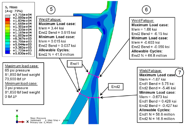
Stress classification lines (SCLs) are a common source of confusion in elastic DBA. An SCL is a path through a section where stresses may be linearized into membrane and bending components. Those components are then classified by their source (such as primary, secondary, or peak) and assessed against the relevant criteria.
The line’s location matters. A path that cuts through the wrong section, crosses a highly three-dimensional region, or does not represent a meaningful shell-like stress distribution can produce results that are difficult to interpret. Stress categories also depend on the cause of the stress, not simply on where a contour plot shows a high value.
That is why “maximum von Mises stress” alone is not a DBA conclusion. The report should show the analysis path, explain why the SCL is appropriate, identify the load and stress classification, and document the acceptance check. If the geometry or stress state makes elastic classification unsuitable, another permitted method, potentially elastic-plastic analysis, may be warranted.
Nozzle reinforcement: the rule check is not the whole load case
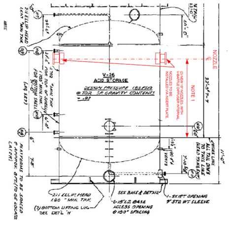
A nozzle may satisfy the applicable pressure-reinforcement requirements and still need further assessment. The area-replacement check addresses pressure reinforcement under its defined rules. It does not, on its own, settle the effect of every combination of piping reactions, thermal displacement, cyclic duty, or local geometry.
The right next step depends on the actual question. A rule-based nozzle check such as WRC Bulletin 537 may be sufficient for a conventional opening. External loads may be handled through applicable calculation methods or, where warranted, a more detailed assessment of the nozzle-to-shell junction. For a rerate or new nozzle, confirm the load basis and acceptance criteria before selecting the method.
A practical decision sequence
Before committing to either path, ask:
Does the applicable Division 1 rule cover the geometry, materials, and service? If yes, DBR may answer the question with less analysis and documentation.
Are the governing loads and cycles represented? Include relevant pressure, piping, thermal, support, wind, seismic, test, and handling cases.
What decision must the analysis support? New design, vendor review, rerate, alteration, continued operation, or repair each has a different basis and deliverable.
Will DBA change the engineering decision? Use it when it can resolve an uncertainty, qualify a nonstandard detail, avoid unjustified over-thickening, or establish a clearer operating or design limit.
Can the result be used within the applicable code and approval framework? Confirm the code edition, documentation expectations, and required coordination before relying on the analysis.
For existing vessels with damage or degradation, distinguish a construction-code design check from a fitness-for-service assessment. An FFS evaluation uses the appropriate API 579-1/ASME FFS-1 method to assess a defined damage mechanism and support a decision to continue operating, monitor, mitigate, repair, or reassess. See Refined Engineering’s Fitness-for-Service services.
Choose the simplest defensible path
For a conventional pressure vessel that fits the applicable rules, Division 1 Design by Rule is often the right and more economical choice. For complex geometry, demanding cyclic or thermal service, highly loaded nozzles, or a rerate that exceeds rule boundaries, Division 2 Design by Analysis may provide the necessary level of evaluation.
The decision should be based on the actual geometry, loads, service history, code basis, and intended use of the result, not on the assumption that more analysis is always better. Refined Engineering supports mechanical design and analysis, including Division 2 Part 5 DBA, as well as rerates, repairs, alterations, and fitness-for-service assessments. Contact our team to discuss the basis and scope for a vessel or equipment evaluation.